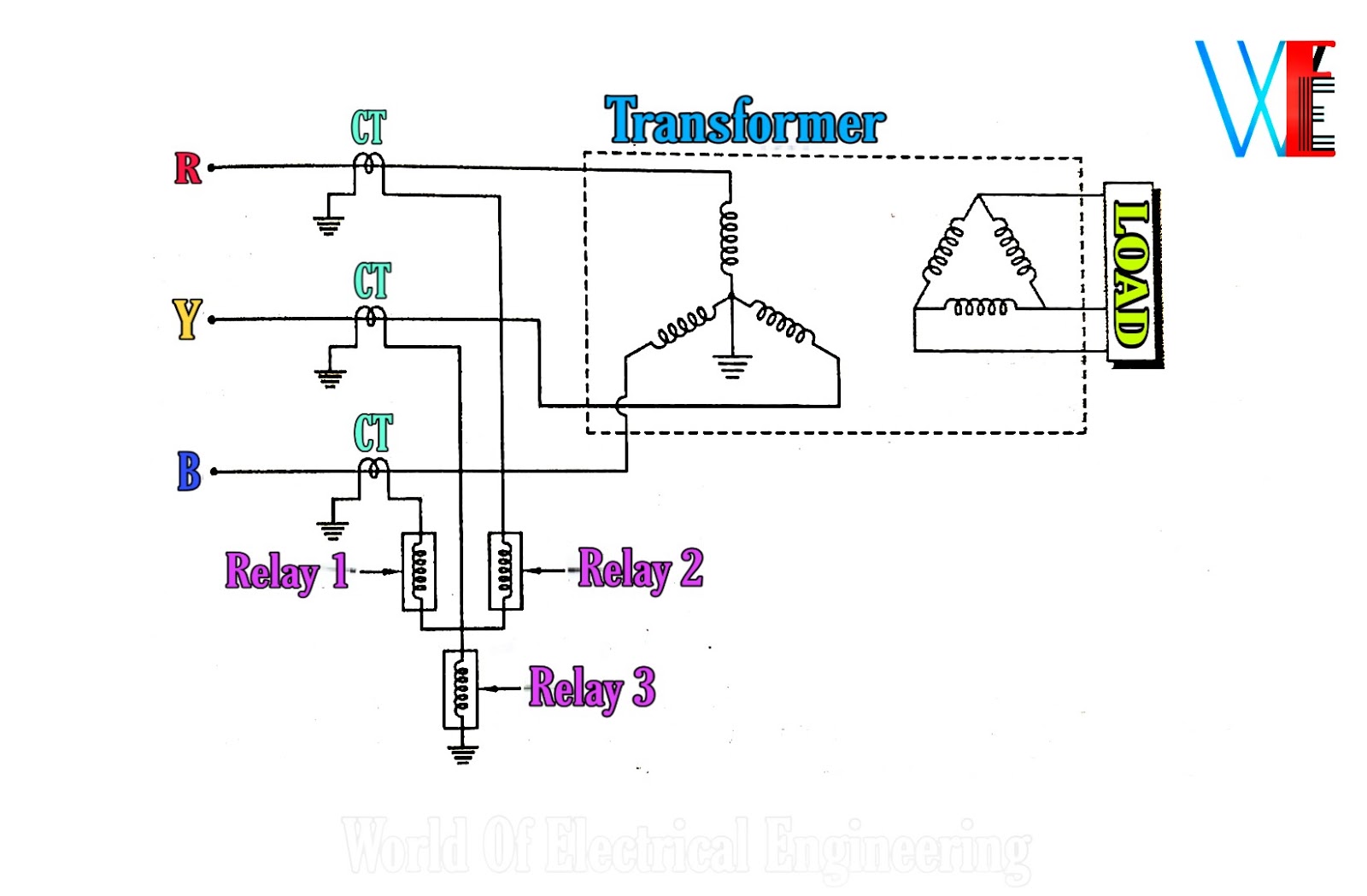
Transformer wiring diagram 480 240 480v diagrams volt wire kva phase 120 single federal pacific secondary primary simple low 500f Generator protection functions and test methods Protection differential generator generators schematic scheme phase arrangement shown three figure
Wiring Toroidal Mains Transformers
480v transformer wiring diagram Transformer 480 wiring protection overcurrent transformers 120 kva volts volt phase wire panel secondary rating large single table less building Wiring transformer transformers power toroidal 110v phase 220v input diagram winding colour parallel series electronics mains two wire colours connections
Transformer delta wye wiring transformers wire phase secondary primary identify two connects supply
Single phase transformer connectionsTransformer differential protection scheme Protection generator diagram line single differential electrical transformer ref relays test over harmonics restrained bias 2nd methods protectionsProtection transformer differential power diagram faults.
480v to 120v transformer wiring diagramCathodic protection rectifier wiring diagram Transformer wiring diagram 480v 120v 120 kva jefferson 240 primary secondary store drawing dry type swgrThree phase transformer connections phasor diagrams.

Control transformer wiring diagram power motor electrical diagrams circuits starter 120v common
Transformer phase single delta wye connections connected connection transformers two diagram wiring figure power why parallel schematics get electrical explainedDifferential protection of generator & alternator Wiring of control power transformer for motor control circuitsExperiment # 1 overcurrent protection of a three.
Transformer transformers 480v connection impedance winding trasformatore autotransformer trifase 120v kva collegamentiTransformer phase diagram wye phasor lead relay electricalacademia Over current protection of transformerCathodic protection rectifier wiring diagram installation system corrosion monitoring patents drawing department systems transformer.

Overcurrent protection fault diagram earth transformer simplified three system power fig
Table 450.3(b) maximum rating of overcurrent protection forHow to identify transformer wiring Connection schematics of voltage transformers for protectiveConnection voltage transformers phase connections schematics vts cts electrical power typical system three protection connected protective applications voltages usually bus.
How to install an electrical transformer with pdf filePower transformer protection and types of faults Transformer protection current over diagram circuitWiring transformer 120v 480v hvac.

Wiring toroidal mains transformers
The autotransformerTransformer differential protection power diagram connection simple scheme current electrical 480v transformer wiring diagramTransformer phase wiring distribution electrical electricity waterheatertimer wires heater volts normally connected connect circuits generator wye stranded turbine.
.


480v Transformer Wiring Diagram

How to identify transformer wiring

Transformer Differential Protection Scheme

Power Transformer Protection and Types of Faults

Over Current Protection Of Transformer

Three Phase Transformer Connections Phasor Diagrams | Electrical Academia

Wiring Toroidal Mains Transformers

480v Transformer Wiring Diagram